- 您现在的位置:买卖IC网 > Sheet目录342 > MCBSTM32EXL (Keil)BOARD EVALUATION FOR STM32F103ZE
�� �
�
�RM0008�
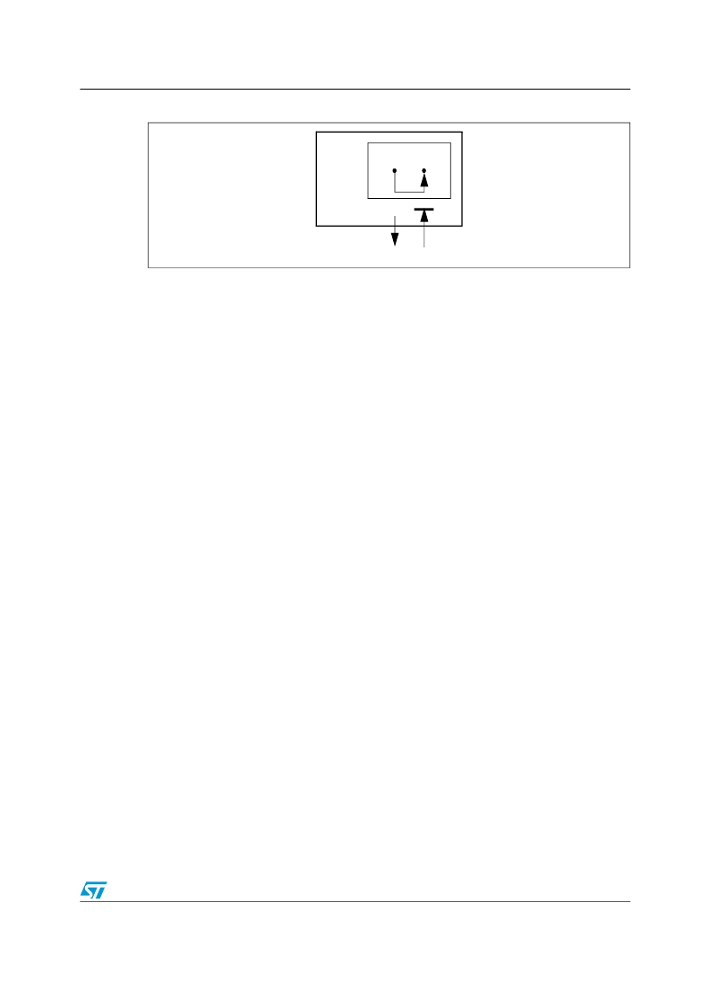
�Figure� 197.� bxCAN� in� combined� mode�
�bxCAN�
�Controller� area� network� (bxCAN)�
�Tx�
�Rx�
�=1�
�CANTX� CANRX�
�22.6�
�STM32F10xxx� in� Debug� mode�
�When� the� microcontroller� enters� the� debug� mode� (Cortex-M3� core� halted),� the� bxCAN�
�continues� to� work� normally� or� stops,� depending� on:�
�●�
�●�
�the� DBG_CAN1_STOP� bit� for� CAN1� or� the� DBG_CAN2_STOP� bit� for� CAN2� in� the� DBG�
�module.� For� more� details,� refer� to� Section� 29.16.2:� Debug� support� for� timers,� watchdog,�
����22.7�
�22.7.1�
�bxCAN� functional� description�
�Transmission� handling�
�In� order� to� transmit� a� message,� the� application� must� select� one� empty� transmit� mailbox,� set�
�up� the� identifier,� the� data� length� code� (DLC)� and� the� data� before� requesting� the� transmission�
�by� setting� the� corresponding� TXRQ� bit� in� the� CAN_TIxR� register.� Once� the� mailbox� has� left�
�empty� state,� the� software� no� longer� has� write� access� to� the� mailbox� registers.� Immediately�
�after� the� TXRQ� bit� has� been� set,� the� mailbox� enters� pending� state� and� waits� to� become� the�
�highest� priority� mailbox,� see� Transmit� Priority� .� As� soon� as� the� mailbox� has� the� highest�
�priority� it� will� be� scheduled� for� transmission.� The� transmission� of� the� message� of� the�
�scheduled� mailbox� will� start� (enter� transmit� state)� when� the� CAN� bus� becomes� idle.� Once�
�the� mailbox� has� been� successfully� transmitted,� it� will� become� empty� again.� The� hardware�
�indicates� a� successful� transmission� by� setting� the� RQCP� and� TXOK� bits� in� the� CAN_TSR�
�register.�
�If� the� transmission� fails,� the� cause� is� indicated� by� the� ALST� bit� in� the� CAN_TSR� register� in�
�case� of� an� Arbitration� Lost,� and/or� the� TERR� bit,� in� case� of� transmission� error� detection.�
�Transmit� priority�
�By� identifier:�
�When� more� than� one� transmit� mailbox� is� pending,� the� transmission� order� is� given� by� the�
�identifier� of� the� message� stored� in� the� mailbox.� The� message� with� the� lowest� identifier� value�
�has� the� highest� priority� according� to� the� arbitration� of� the� CAN� protocol.� If� the� identifier�
�values� are� equal,� the� lower� mailbox� number� will� be� scheduled� first.�
�By� transmit� request� order:�
�Doc� ID� 13902� Rev� 9�
�549/995�
�发布紧急采购,3分钟左右您将得到回复。
相关PDF资料
MCBTMPM330
BOARD EVAL TOSHIBA TMPM330 SER
MCIMX25WPDKJ
KIT DEVELOPMENT WINCE IMX25
MCIMX53-START-R
KIT DEVELOPMENT I.MX53
MCM69C432TQ20
IC CAM 1MB 50MHZ 100LQFP
MCP1401T-E/OT
IC MOSFET DRVR INV 500MA SOT23-5
MCP1403T-E/MF
IC MOSFET DRIVER 4.5A DUAL 8DFN
MCP1406-E/SN
IC MOSFET DVR 6A 8SOIC
MCP14628T-E/MF
IC MOSFET DVR 2A SYNC BUCK 8-DFN
相关代理商/技术参数
MCBSTM32EXLU
功能描述:开发板和工具包 - ARM EVAL BOARD + ULINK2 FOR STM32F103ZG
RoHS:否 制造商:Arduino 产品:Development Boards 工具用于评估:ATSAM3X8EA-AU 核心:ARM Cortex M3 接口类型:DAC, ICSP, JTAG, UART, USB 工作电源电压:3.3 V
MCBSTM32EXLU-ED
制造商:ARM Ltd 功能描述:KEIL STM STM32EXL EVAL BOARD
MCBSTM32EXLUME
功能描述:开发板和工具包 - ARM EVAL BOARD + ULINKME FOR STM32F103ZG
RoHS:否 制造商:Arduino 产品:Development Boards 工具用于评估:ATSAM3X8EA-AU 核心:ARM Cortex M3 接口类型:DAC, ICSP, JTAG, UART, USB 工作电源电压:3.3 V
MCBSTM32F200
功能描述:开发板和工具包 - ARM EVAL BOARD FOR STM STM32F207IG
RoHS:否 制造商:Arduino 产品:Development Boards 工具用于评估:ATSAM3X8EA-AU 核心:ARM Cortex M3 接口类型:DAC, ICSP, JTAG, UART, USB 工作电源电压:3.3 V
MCBSTM32F200U
功能描述:开发板和工具包 - ARM EVAL BOARD FOR STM STM32F207IG + ULINK2
RoHS:否 制造商:Arduino 产品:Development Boards 工具用于评估:ATSAM3X8EA-AU 核心:ARM Cortex M3 接口类型:DAC, ICSP, JTAG, UART, USB 工作电源电压:3.3 V
MCBSTM32F200UME
功能描述:开发板和工具包 - ARM EVAL BOARD FOR STM STM32F207IG ULINK-ME
RoHS:否 制造商:Arduino 产品:Development Boards 工具用于评估:ATSAM3X8EA-AU 核心:ARM Cortex M3 接口类型:DAC, ICSP, JTAG, UART, USB 工作电源电压:3.3 V
MCBSTM32F200UME-ED
制造商:ARM Ltd 功能描述:KEIL STM32F207IG EVAL BOARD
MCBSTM32F400
功能描述:开发板和工具包 - ARM EVAL BOARD FOR STM STM32F407IG
RoHS:否 制造商:Arduino 产品:Development Boards 工具用于评估:ATSAM3X8EA-AU 核心:ARM Cortex M3 接口类型:DAC, ICSP, JTAG, UART, USB 工作电源电压:3.3 V